The Hallicrafters Company
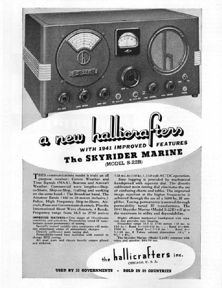
The Hallicrafters Company of Chicago, IL manufactured several models of receivers and AM transceivers specifically intended for marine radio use during the period from 1938 to 1946. Some of the receivers may have found inland marine use and the transceivers certainly did. The marine transceivers were the HT-3, HT-8, HT-11, HT-12 and HT-14. The receivers designed with marine use in mind included the S-22, S-22R, S-30 (Radio Compass), and the S-51 (a 1950s design). The links are to advertisements for the units.
 |
The
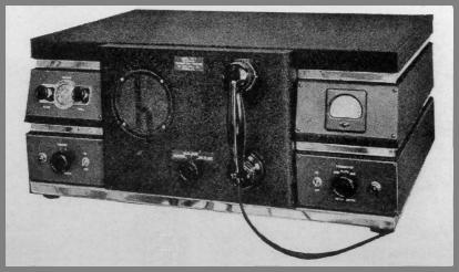
HT-3 was a 50 Watt marine transceiver of 1938 vintage. The
transmitter operated on 3 crystal controlled channels in the 2.1 to 2.9
MHz band. The two-band, six-tube, tunable receiver covered
the broadcast band and the 1.9 to 3.1 MHz marine band. The unit was
powered from 12 or 32 VDC depending on the power supply
choice. |
|---|---|
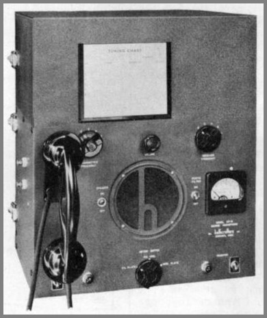 |
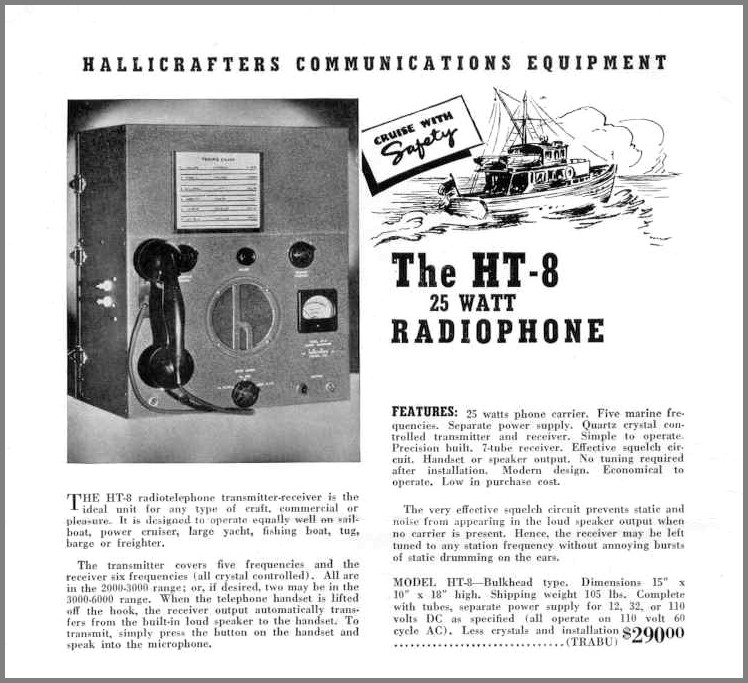
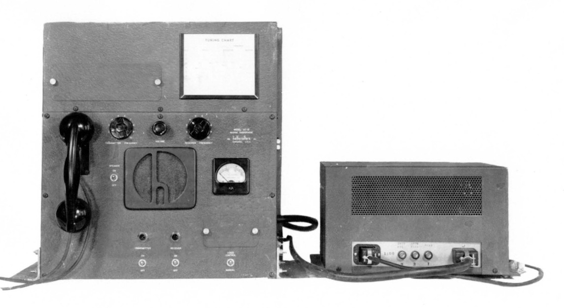
The
HT-8 shown on the left or above was a 25 W marine transceiver of 1939 vintage. The Superhetrodyne
receiver had a seven tubes and the transmitter had four. A rectifier
completed the 12 tube lineup. It operated on any of 5 Xtal controlled
channels in the 2.1 to 2.8 MHz range and, with slight modifications, up
to 6.6 MHz. The receiver also had one additional channel for a 2 MHz
marine weather frequency. Later production of the unit had a socket to
connect an external Western Electric type 104A ringer unit for
selective calling. The purchaser could specify a power supply for
operation on either 120VAC or 12VDC. The power supplies were external
units, and 12 VDC supply was dynamotor operated. |
|---|---|
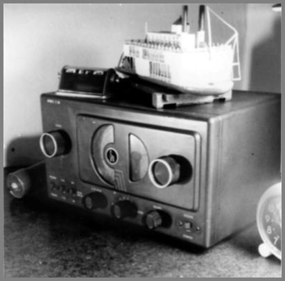
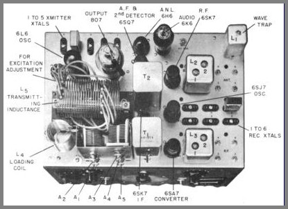 HT-8 top view |
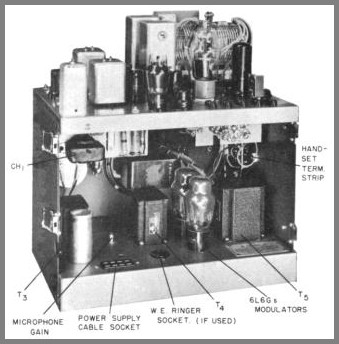 HT-8 rear view |
|---|---|
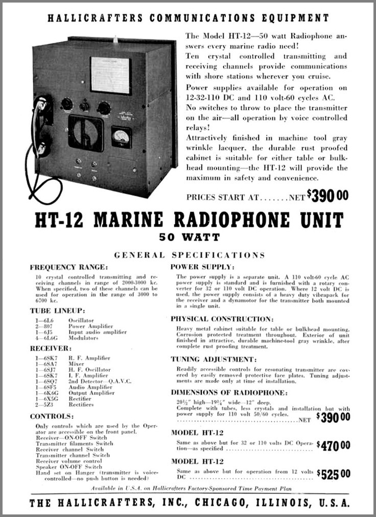
Hallicrafters HT-12 a 50 Watt unit with AC Power Supply HT-12 Advertisement & Specifications>
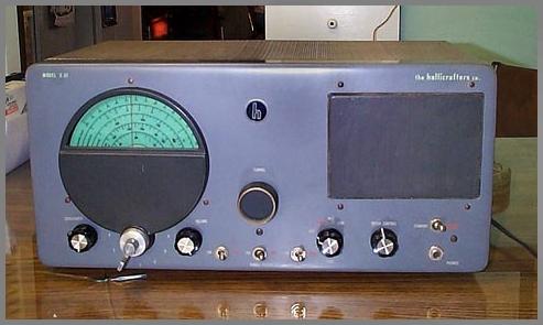
 It isn't a marine unit, it's my first SW RX a S-38 - Taken 6/14/1949 |
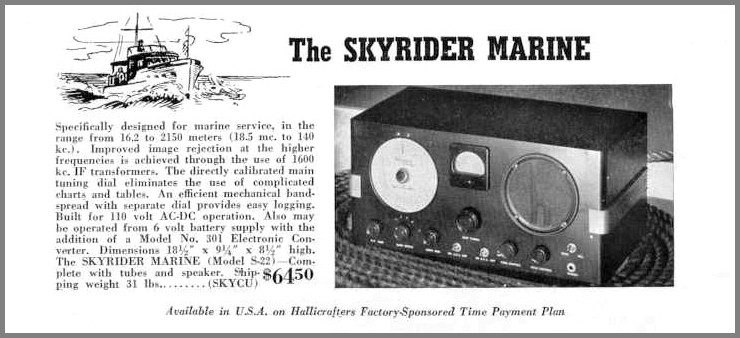
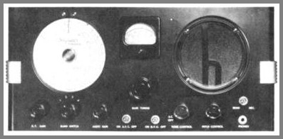 S-22
photo from the S-22 instruction book. |
|---|---|
 |
 Above:
The S-51 Sea Farer. General Coverage Receiver, Single Conversion. 4
bands 0.132-13MHz, has also 3 fixed frequencies. IF 455kHz. 10 tubes.
AC/DC. Production year 1947-49. Image and information from LA5KI's
great Hallicrafters Gallery. (Note: Other sources say this is a 1950s model.)
|
|---|---|
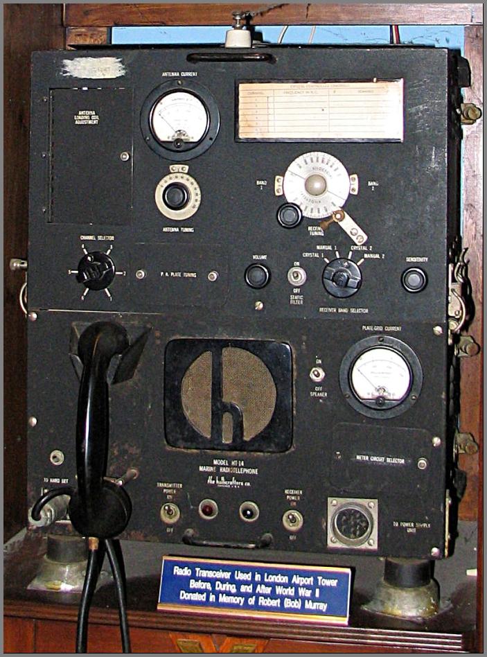
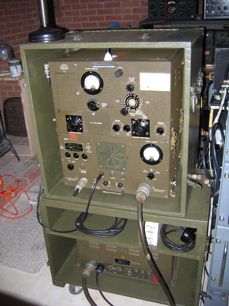
The HT-14 (military version) shown above had 15 tubes. The TX was 45 watts with two 807 tubes in the final and 6 crystal-controlled channels between 1.68 & 4.45 MHz. The RX had two crystal and two VFO switch positions. The IF was 385 kHz. Operated from either 110 VAC, or 12, 32 or 110 VDC depending on the user-specified power supply. The slightly different civilian version was called the Commodore.
Doran "Jeep" Platt, K3HVG supplied these photos of the military version of the Hallicrafters HT-14 - the SCR-543 radio set. The photos are of the "D" model of this equipment. Unlike earlier models of the SCR-543 (BC-669), the "D: model includes the ability to control an external antenna coupler as well as local control for a gas generator. The home-built transit cases shown in the photos are replicas of the original ones.
Back to the Equipment Page
Except as noted here most of the site's content is in the public domain.
Last Updated Home